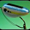
m_vandorn Posted November 14, 2015 Report Share Posted November 14, 2015 Solar powered and battery powered vibrating fishing lures are something I’ve been working on since the late part of 2012. In this last year I finally figured out how to do the battery powered version. The difficulty with the battery powered version was figuring out how to seal the battery compartment & Motor compartment so water did not get inside. The information I am providing will give, anyone interested, a jump start on the learning curve I’ve gone through. First, before I get started, I want to tell you more about the successful testing of my lures. Over the last two years, I have had several people, some that have bought and loved my lures and others that are personal friend. They have been tested in Maryland, North Carolina, Georgia, Florida, California and in NSW Australia. They have been tested against other electronic type lures, such as the Livingston lures and a few others that use LED lights. In every case, my vibrating lures have outperformed in attracting fish. To test the lure’s fish attracting ability, I’d simply throw the different lures out and watch, with my polarized sunglasses on, to see if small bait fish would be drawn to the lure. It’s really quite amazing to see them gather around my lure as if mesmerized by the sound/vibrations. Neither of the other lures, including the Livingston lures had the same results. After I started putting legs on my lures, such as my popper and winged bugs, larger size panfish would not only be mesmerized, by the sound, they would strike. A few of my friends have told me that they have caught bass, with the battery powered versions, where bass were drawn to the lure from as far away as 50 feet. I have personally not seen this, perhaps because the waters, here in Georgia, are not so clear. Originally, my work was focused on making small, bug like, lures. I assumed fish were attracted to the sound and vibrations like they are to bugs. But, in, the most recent test, in Australia, in saltwater where visibility is up to 100 feet, a weighted jig type prototype lure was provided to test and in the words of my friend, “The fish were not only attracted, they were killing it.” So, it appears, the vibrations and sound from these motors are not only good for topwater lures, but other lures as well. My final comment before getting started is this: Even with all the testing and positive results, one fact still remains true; the lure design and look is still very important. From my experience and observations, the vibrations and noise from my lures do, in fact, provide an advantage of attracting the attentions of fish, but if the lure or the action, of the lure, does not look like something a fish would want to kill or eat, it is less likely the fish will strike. So, let’s get started: The picture below shows parts I bought and parts I made to make both the solar powered and battery powered lure versions: Solar Powered Cockroach: Purchased on eBay 1.5 ml plastic vial - Purchased on eBay Spring from a retractable ballpoint pen. Spring, handmade with 0.024” stainless wire - from Lure Parts Online Molded part for motor contact springs and motor - master part made by me, mold made with Alumilite silicone rubber and the part cast with Alumilite white and yellow die. E6000 glue for sealing the wires holes in the molded part and for lightly anchoring the motor into the molded part. There are, of course, other things made and purchased to make my master lures, my hooks, through wire, etc. I am sure these items will be explained as I continue to explain the method of making the lures. I will be posting more information on how these parts are made, shaped and used to make the motor / battery compartment of my lures. I think this is a good start to get you thinking. 1 Quote Link to comment Share on other sites More sharing options...
m_vandorn Posted November 14, 2015 Author Report Share Posted November 14, 2015 I believe there is need for a little more information before I continue on the how-to of this forum. Regarding the motor chosen for my lures. I was fortunate to find the specific motor that is in these solar powered toys. They are 1.5V motors which works well with the AG3/LR41 button cell battery I use. What makes the motors so perfect for this is, the motor starts to work at 0.8V which means you will actually get a longer run life with the battery as the battery starts to run down. Another issue that many might be wondering about is the battery life, ie. how long does the battery last. At first this was a concern for me as well, one that almost gave me caused not to design and make the battery powered lure versions. The answer is: A fully charged AG3/LR41 battery will last 12 - 15 minutes. The way I overcame the issue of a potentially short run time was by developing a design where the battery can be very quickly changed. That and a very low cost for these batteries has made what was a seemingly short battery runtime a non-issue. Case in point, with a new battery in hand, the used battery can be replaced in under 8 seconds and the cost for fully charged batteries are under $0.06 each on eBay. I will warn, however, that some vendors, on eBay, will sell old, shelf life expired, not fully charged batteries for as low as $0.03 each. To me, it is worth paying a little bit more for longer lasting batteries, especially when the price is so low. Now, one last note, before I begin the how to. There is one thing that amplifies the noise in my lures which creates the great fish attracting sound. It is something for which I completed a patent search and apply for a patented. I install the motor such that the body of the motor vibrates against an internal side wall. The motor to wall contacting the wall increased both the vibrations and sound coming out of the lure. I have tested lures where the motor is suspended freely and vibrations are merely a result of the out-of-balance wheel on the motor and found that the fish attracting sound is greatly reduced,. So, I am all for people making their own lures using information I’ve provided but if a company mass produces lures with my patented pending idea, I will have no choice but to litigate. I am sorry for the downer of the last note. I just that I have put a lot of work into my designs and it is my hope that I will soon have my products mass produced and sold in retail outlets. Quote Link to comment Share on other sites More sharing options...
Travis Posted November 14, 2015 Report Share Posted November 14, 2015 (edited) So, I am all for people making their own lures using information I’ve provided but if a company mass produces lures with my patented pending idea, I will have no choice but to litigate. I am sorry for the downer of the last note. I just that I have put a lot of work into my designs and it is my hope that I will soon have my products mass produced and sold in retail outlets. Hmmm.....good luck on that one. http://www.alivelure.com/ http://www.remoralure.com/ https://www.google.com/patents/US6581319 http://www.google.com/patents/US6804909 Also several others covering oscillating motion and different forms of vibration. Edited November 14, 2015 by Travis Quote Link to comment Share on other sites More sharing options...
m_vandorn Posted November 14, 2015 Author Report Share Posted November 14, 2015 I get your point Travis, but I can tell you I have investigated the methods used by my competition and none of them do what I have applied my patent for. I will also explain that I have tested my lures against those as well and they do not even come close the attracting fish the way mine does. The Alive lure was especially disappointing to me. I know what I am saying is just words right now, but I will be excited when other make lures and test it. There is one more thing. I also understand it is much more difficult to litigate and win but I have to put it out there to let people know I will not simply roll over. With that said, I am glad you have joined the discussion. Quote Link to comment Share on other sites More sharing options...
m_vandorn Posted November 14, 2015 Author Report Share Posted November 14, 2015 By-the-way, Travis Thank you for posting the two patents. When I paid for my patent search, these patents were found and they suspend the motors freely. The focus of my patent is causing the motor to strike one or more walls around the motor. What is important here though, is I really don't want this forum to be totally focused on intellectual property. I just started with that information to get it out of the way. So, I will continue with more information shortly. 1 Quote Link to comment Share on other sites More sharing options...
mark poulson Posted November 15, 2015 Report Share Posted November 15, 2015 Wow, this looks like a great thread in the making! Thanks for being willing to share all your hard work. 1 Quote Link to comment Share on other sites More sharing options...
JRammit Posted November 15, 2015 Report Share Posted November 15, 2015 I think youre off to a great start!... Maybe even a step ahead Props for having the courage to share here!... Thats what we're all about 1 Quote Link to comment Share on other sites More sharing options...
Vodkaman Posted November 15, 2015 Report Share Posted November 15, 2015 Very interesting read. Is the battery type available as a rechargeable. I am thinking that a solar cell charger would keep a set of 4 batteries going all day, even a cloudy day. Another alternative would be one of those hi-capacity rechargeable phone chargers. Dave 1 Quote Link to comment Share on other sites More sharing options...
m_vandorn Posted November 15, 2015 Author Report Share Posted November 15, 2015 There is a rechargeable battery type, usually used for hearing aids but the charger runs $150 - $250, and I'm not sure if the battery is a 1.5V. It might be a 3V which is two high for this particular motor. When I first started looking to do this, what you want to do was what I was thinking about, but I found it cost prohibitive. For me, it was best to go the direction I did. There are many ways to go though. I'm sure I have not figured them all out. 1 Quote Link to comment Share on other sites More sharing options...
Vodkaman Posted November 15, 2015 Report Share Posted November 15, 2015 (edited) I knew that you would have looked into this, so I didn't bother searching. That price for the charger is ridiculous, but promising, that rechargeable batteries are available. It is just a matter of manipulating the voltage and current from a popular/cheap charger, down to what you require. This is a project for down the line, along with solar cells as a charger source. I just checked, suitable solar cells are available at around $1. Dave Edited November 15, 2015 by Vodkaman Quote Link to comment Share on other sites More sharing options...
m_vandorn Posted November 15, 2015 Author Report Share Posted November 15, 2015 It sounds like you have experience working electronics, Vodkaman. I have looked for ways to extend battery life even longer and have not found a way to do it. I thought of using a zener diode to limit current or using a capacitor but I'm not sure if that would work. What do you think? Quote Link to comment Share on other sites More sharing options...
Vodkaman Posted November 15, 2015 Report Share Posted November 15, 2015 Yes, I occasionally do hobby electronics, although it has been many years since my last project. For battery life extension, rather than having a continuously running motor, I would try a pulse operation, say run for 0.25 seconds once per second. This would immediately increase your battery life by X4. Of course, More space would be required for the electronics and you would have to ask the fish if they approved of this new operation. The electronics are simple, based on a 555 chip and a few passive components. Lots of information on the internet. You could develop the idea using standard components, easy to work with, but for production, you would want to go to surface mount as they are much smaller. I have not worked with surface mount. Another problem is the 555 runs on a minimum voltage of 4.5V, but there may be other ways of achieving the pulse with other components. I just did a quick search and found this circuit. On the face of it, this is not applicable. It is for a high frequency, high voltage generated from a low voltage. BUT, get rid of T1 and play around with the values of R1 and C1 and this may solve your problem. This works by charging and discharging a capacitor C1. The size of the capacitor and resistor controls the time of the cycle. With the introduction of a couple of diodes and another resistor, you can control the charge and discharge times separately, thus getting your X4 battery saving. Just a couple of ideas. DAve 1 Quote Link to comment Share on other sites More sharing options...
m_vandorn Posted November 15, 2015 Author Report Share Posted November 15, 2015 OK, let me continue. Another good thing about my design, in my opinion is the assembly of the motor unit does not require any solder joints. The molded part is made so that two small holes are drilled into the molded part for the motor leads to pass through. Then the two contact springs are pressed over the leads thus creating the required contact between the leads and the battery contacts. Hmmm, I was going to post a picture to show what I mean and I'm not sure how to do it. There was a button to add attachments when I posted the first message. Quote Link to comment Share on other sites More sharing options...
Vodkaman Posted November 15, 2015 Report Share Posted November 15, 2015 (edited) As for your zener idea to limit the current, well I have no experience with zeners and current limiters. Again, lots on the web. Do a search using key words and use 'circuit' as a key word otherwise you just get products. Keep in mind the motor's requirements. There will be a minimum operating voltage and it will draw a certain current. If you prevent this current from being drawn, the motor will likely stall. All these things have to be tried/prototyped/tested to find a solution that works. Be prepared for lots of failures. To access the photo posting options, press 'more reply options' bottom right. Dave Edited November 15, 2015 by Vodkaman Quote Link to comment Share on other sites More sharing options...
m_vandorn Posted November 15, 2015 Author Report Share Posted November 15, 2015 Yes, I have looked into what your talking about. Like you said the 555 requires higher voltage and the other options are there and I haven't had time to work out the components needed. I did a little work with it and found I was having to increase the size of the lure. I will be making larger lures in the future so I will work on it then. Thanks for the info. Quote Link to comment Share on other sites More sharing options...
m_vandorn Posted November 15, 2015 Author Report Share Posted November 15, 2015 This motor runs on very low current, 45 mA max, so there is room to restrict current and still have good vibrating strength. The solar cells that come with these motors produce a max 1V they vary from 0.85 to 1V. The 1.5V that come from the AG3/LR41 button really makes these motors buzz. Quote Link to comment Share on other sites More sharing options...
m_vandorn Posted November 15, 2015 Author Report Share Posted November 15, 2015 To continue, I need to post more pictures. I'm new to doing this. Can someone help me on how to do it? I don't see a button for adding attachments. Quote Link to comment Share on other sites More sharing options...
Vodkaman Posted November 15, 2015 Report Share Posted November 15, 2015 Press the 'more reply options' button, bottom right. Dave 1 Quote Link to comment Share on other sites More sharing options...
m_vandorn Posted November 15, 2015 Author Report Share Posted November 15, 2015 Thanks Vodkaman, OK, There are a few pictures below so you can see what I'm talking about. The lead wires are pushed through the bottom of the molded part, one lead on the outside and one on the inside and the contact springs are pressed over the leads. Note: a small about of E6000 glue is applied to the shielding of the leads and the bottom of the motor to seal the drilled holes and anchor the motor to the plug. Then the molded part, lets just call it a plug, with the motor and contact springs attached are pressed into the cut off part of the plastic vial. Note: the plug is sized so it is a press fit into the vial. 1 Quote Link to comment Share on other sites More sharing options...
m_vandorn Posted November 15, 2015 Author Report Share Posted November 15, 2015 I use a tool I made to press the motor assembly/plug in place. The tool sets the correct depth to assure the battery seats properly in place when the cap is screwed on. I'll take a picture of the tool tomorrow and post it. Below you will see how the lure looks before I press the unit in place. Before I install the unit, I make sure to rough up the outside of the vial section so the plastic epoxy adheres to it. Note: I paint and clearcoat the lure bodies before installing the motor assy. The pictures I show with the motor assy with an unpainted body. I also show bodies painted and clear coated without the motor assy. I'm sure there will questions from this, so ask away. 1 Quote Link to comment Share on other sites More sharing options...
Vodkaman Posted November 15, 2015 Report Share Posted November 15, 2015 Electronics in such a small body is always difficult, given the additional problems of sealing. Well designed and engineered. Dave 2 Quote Link to comment Share on other sites More sharing options...
diemai Posted November 15, 2015 Report Share Posted November 15, 2015 @ m-vandorn I may not try to build such a lure after your kindly shared instructíons , as I'm not too smart about electronics , ......but stlll I'd like to thank you for your willingness to share your design in here , .....it's people like you making this site so extraordinary . Good luck with commercializing your design , ....best greetings , Dieter 2 Quote Link to comment Share on other sites More sharing options...
m_vandorn Posted November 15, 2015 Author Report Share Posted November 15, 2015 Thank you, Dieter, Regarding the concern about lacking knowledge of electronics, I too am no genius when it comes to this. I've learned a little in my quest to make my lures, but in actuality, this design has very little electrical difficulty. There are no other electronic components than a motor and a battery. Just think of the contact springs and connectors to the motor for the battery. The fact is, I labored for the longest time trying to make the lure more complicated than it had to be. I first started by trying to create an intermittent timer circuit and by trying to use a solar cell, on the lure to charge a battery. In the end, I ended up with a simple design where I designed a quick way to replace the battery and that is it. Either way, if you try to make a similar lure or not, thank you for your kind comment Michael 2 Quote Link to comment Share on other sites More sharing options...
Vodkaman Posted November 15, 2015 Report Share Posted November 15, 2015 m-vandorn - thinking back on the solar charger idea: The thing about charging batteries, is that they do not want a smooth constant voltage, in fact the rougher the better. So the circuit that I linked combined with a $1 solar cell would probably do quite nicely as a charger, again removing the T1 coils. This would give you a charger to test for a parts cost of probably less than $2 plus a box. Certainly a lot more appealing than $250, of course, it might not work, but has to be worth a test some day. Dave 1 Quote Link to comment Share on other sites More sharing options...
m_vandorn Posted November 15, 2015 Author Report Share Posted November 15, 2015 Vodkaman, It is certainly something to consider. I'm not sure how long it takes to charge the batteries, so another thing to consider is the number of batteries you would need to keep in cue. Charging batteries rather than using and throwing batteries away would be a better, cleaner solution. 1 Quote Link to comment Share on other sites More sharing options...