Dgfidler
-
Posts
8 -
Joined
-
Last visited
-
Days Won
1
Content Type
Profiles
Articles
TU Classifieds
Glossary
Website Links
Forums
Gallery
Store
Everything posted by Dgfidler
-
Need an accurate RC 1.5 and maybe a 2.5 stl
Dgfidler replied to Mad Moose Baits's topic in Hard Baits
Aulrich. I’m not sure if you already bought your electronics, but if you have not, I bought a 4 axis turnkey kit from G3CNC. it’s a small, possibly one man shop run by a guy named Stacy. He walked me through wiring issues and I had no problems getting up and running on my homemade router. I feel I can use the electronics box he built for me as a good example to do the next machine on my own. If you’re planning to make lures with your CNC, you are going to be pleasantly surprised by the quality once you get up to speed. I have been debating creating a YouTube channel on the subject because I feel very strongly it’s hands down the best method to produce wooden lures if you’re willing to make the time investment. It was so much trial and error getting there that makes me hesitate doing that.
-
I was browsing lure patents and came across one that I believe embodies the twisted wire eyes a lot of us put in our lures. The patent was issued on April 9. 2019 and its number is US 10,251,381 B1. I was really surprised to see a recent patent issued for something that yhas been in the public domain for possibly decades. Use an allen key instead of screwdriver to avoid violating it? The synopsis is: A method of creating an eye loop can be done by use of a screwdriver, pliers, wire, and optionally a lure to be attached. The first step comprises bending wire around a screwdriver to create pre-eye loop shape/form wire and optionally inserting a distal end of wire into the lure or other fishing tackle that is desired to be attached to the fishing line. Then positioning the pre-eye loop shaped wire in the pliers so the distal (or tag line) end of the wire extends out the left side of the pliers and the proximal (or leader line end of the wire extends out the rear end of the pliers. In the next step, simultaneously turning the pre-eye loop form and pliers in opposite directions, preferably 1⁄4 turns at a time, and pref- erably up to 10 one-quarter turns to create the desired wire eye loop and optionally the wire is attached to the fishing line via the wire eye loop.
-
While I’m no hard bait expert, I have mastered the technical details of going from a CAD design in Fusion 360 to CAM Toolpaths and can produce a lure I can experiment with. I think the repeatable nature of this will allow me to ‘fiddle’ with this design until it performs exactly like I want. It takes 22 minutes of machine time to produce the lure I posted. Is anyone here interested in me starting a YouTube channel where I document this process and future projects? Here are the lures I have planned: Small 3-5 -4 inch Muskie crankbait 5 inch Shad Muskie bait with aluminum lip that’s balanced for that lip crappie crankbait set like bandit 100/200/300 but my own design Shad Rap 5 &7 like but my own design Perfectly Balanced Muskie Glide Bait perfectly balanced jointed swim bait (I realized how a CNC built bait can be perfectly balanced/tuned with resin injection when Nate Marling cut a Roman Mother on two on a YouTube video he pondered why it had internal pockets with resin) a big deep diving crankbait that can be trolled 10-20mph to use for wahoo Is there interest in seeing this on YouTube? It took me two years of my spare time to figure this out. Now it seems simple to me, but there’s really very little information out there. The best info I found focused on electric guitar body building on the CNC. A simple fishing lure might be more complex than the woodwork for an electric guitar I might argue
-
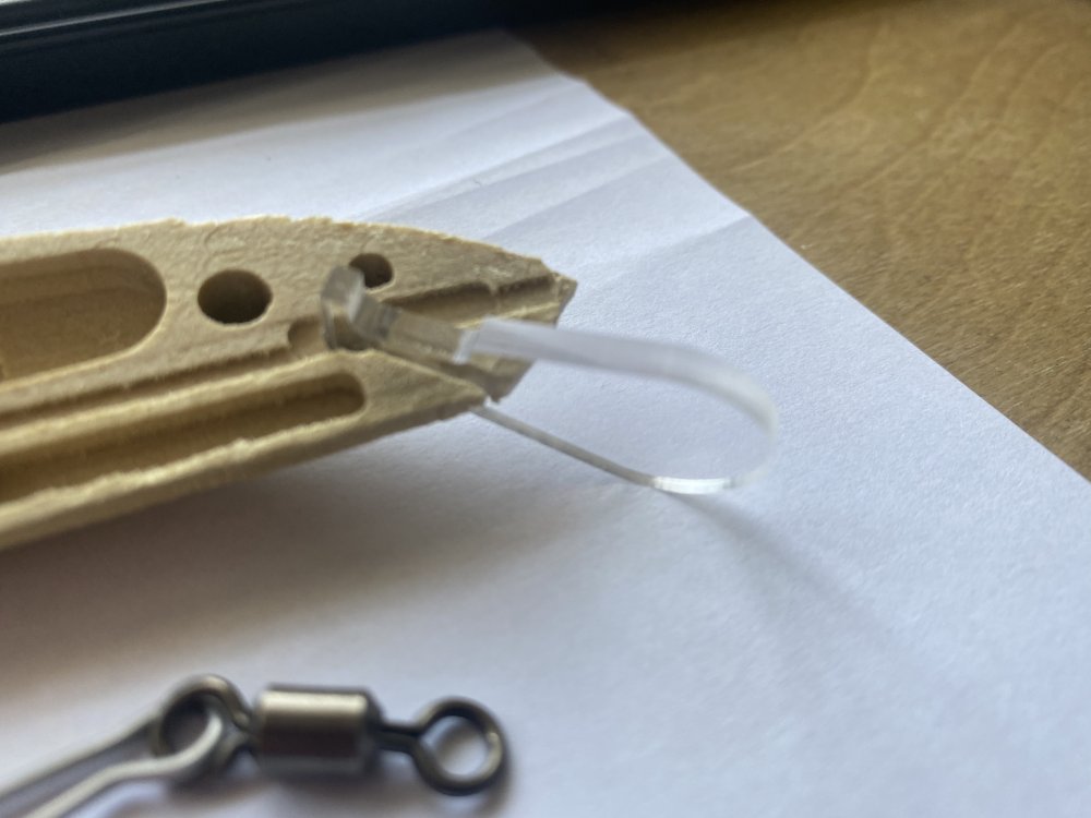
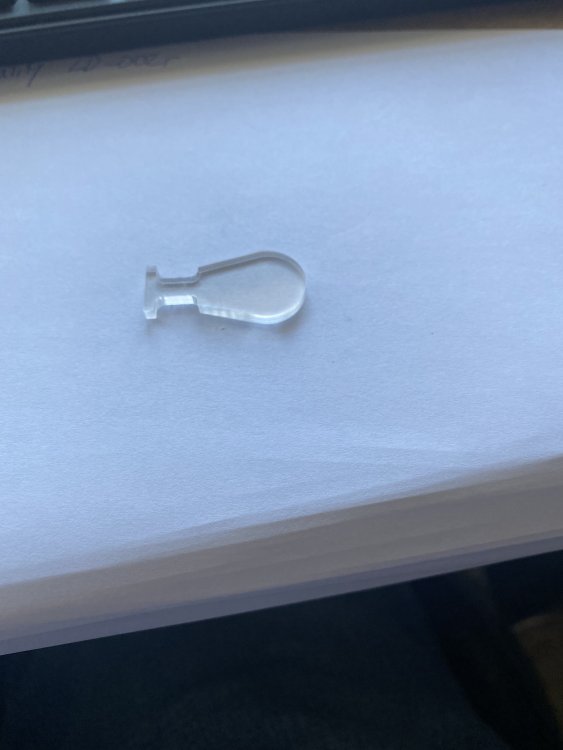
I’m doing some interesting stuff with the lip where it gets locked in when you glue the two halves together. I think it’s cool.
-
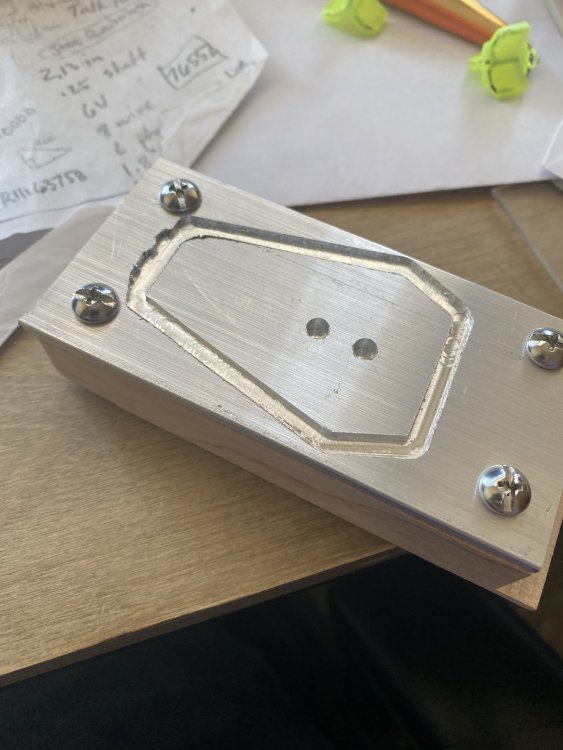
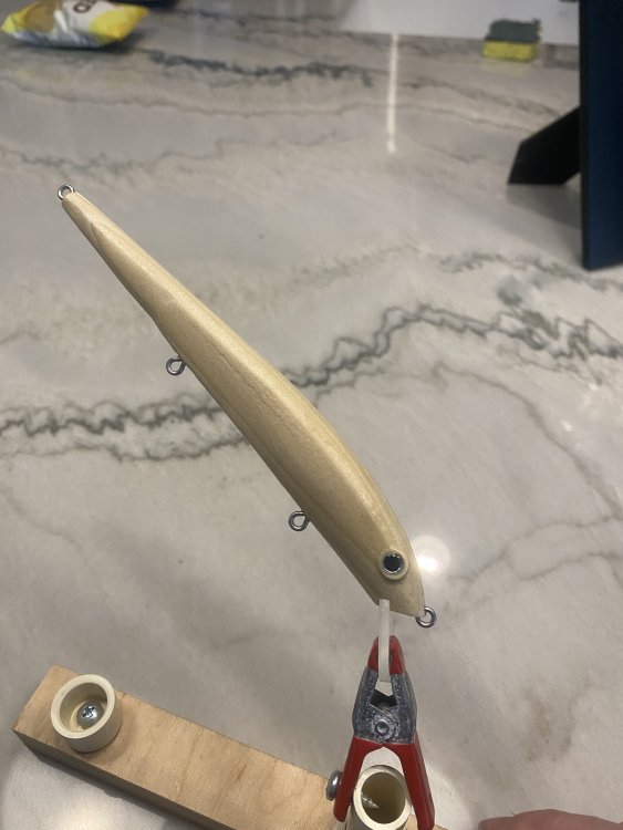
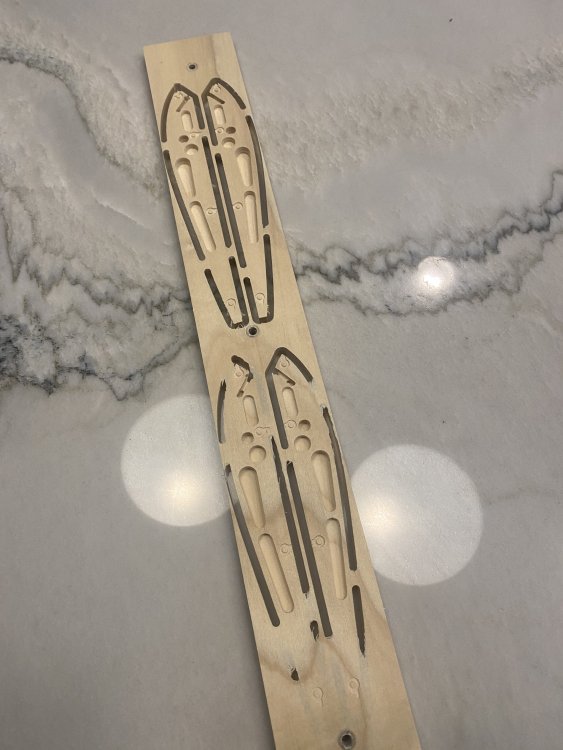
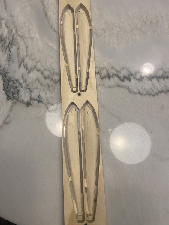
The key to making lures on your hobby CNC machine lies in precise and repeatable work holding. I started having success once I drilled some alignment dowels into my spoilboard that are used to align a fixture plate that I screw the stock down on. The screws holding the stock are aligned on the Y axis and it’s extremely important these are perfectly aligned with the axis or the two pieces don’t align once the milling is complete. This seven inch lure is going to be a cold water walleye crankbait. I am going through a trial and error process to balance it and get it very slightly under suspending weight. I want to be able to stop reeling and have the lure just sit there level. I will inject a small amount of epoxy into one of the upper cavities and then let that epoxy heal or plug the hole. That’s my plan at least.
-
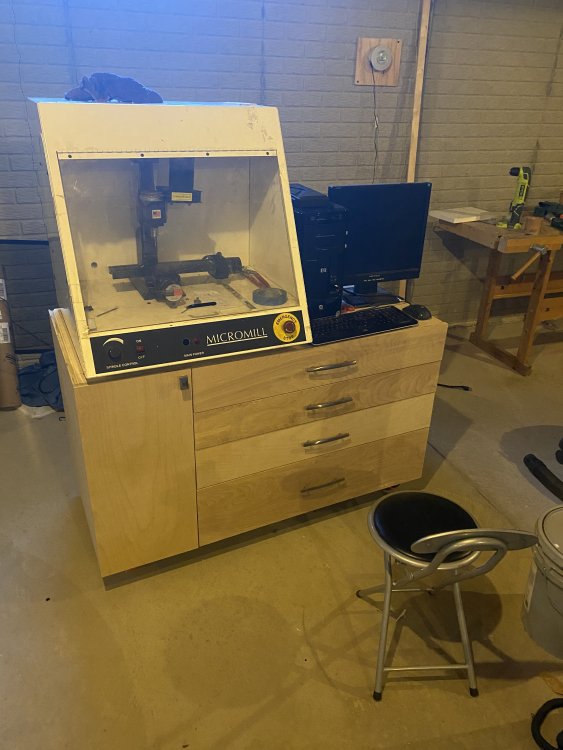
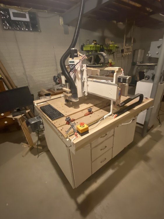
I have had some success with my CNC lure making. I ultimately found the little Sherline based CNC mill had too small of a work envelope. Then I went down a rabbit hole. I decided I needed CNC Router and wanted a 2 x 3 ft XY range so I could use it for woodworking also. To keep costs down, I built my own from a kit called Gatton CNC. Here’s the machine I built.
-
The software I use to generate the tool paths allow you to pick a ‘vector’, in this case the circle defining the eye socket, and choose the tool. I’ll use a flat bottomed end mill. The whole thing is much more manual than I thought it’d be when I first started reading about it. I expected the software to allow me to tell it what tools are available and it’d figure out the optimal way to mill it. Maybe that’s the next generation of CAM. The reality is you have to decide what tools to use and the software will generate tool paths to remove the most material given your choice. My educational background was computer science which included basic physics classes. Much of that coursework revolved around ‘mass’, however the effect of the air (or in this case water and air) were mostly ignored. Maybe some limited study of coefficient of friction and the fact that friction on a moving object through the air is exponential, etc. Anyway, the concept of buoyancy was not covered and I completely overlooked it. I’d guess it’s related to the material’s relative density as compared to water. It does kind of ‘bust my bubble’ that COG is not the end all measure. I’m sure there is some software that would incorporate this concept, but certainly not for free! In software development, when you start working with a new language, the first project is customarily a simple process to output the words ‘hello world’ on the screen, printed page, in the file, or whatever the output medium is. This is my ‘hello world’ project. It starts at the level I had moderate success in my own lure making. Once I started trying to do more complex shapes, my lack of carving skills and left hand/right hand bias created lures that were asymmetric; they float at odd angles, dive to the right, dive to the left. Once I have worked out the workflow and build process in this simple design, I intend to make crankbaits that I actually fish with. One of the main ‘problems’ I hope to solve is during the summer, we take off the shelf floating deep diving crankbaits and troll them behind 300 feet of monel wire to get them to run at 50 feet down. I hate the wire. My kids backlash the reels, it kinks; in general it takes the fun out of our fishing, but it’s highly effective so we do it. Some people believe the wire gives a unique vertical presentation, but I hope to design and build a box of crankbaits that dive to 50 feet with 10lb mono line with 300 feet or less of line out. My first experiments will be to determine whether it’s possible to build a ‘heavy’, non floating deep diver. Why do we need a floating lure if our intention is to fish it 50 down? I think we don’t, but that’s what they sell. This is what motivates me to build my own lures - to obtain something that’s not for sale. Even if it’s still trial and error, the machines will let me experiment with test lures having less variance. The worst type of variance is variance you’re not aware of; carving the left side less than the right because you’re right handed for example.
-
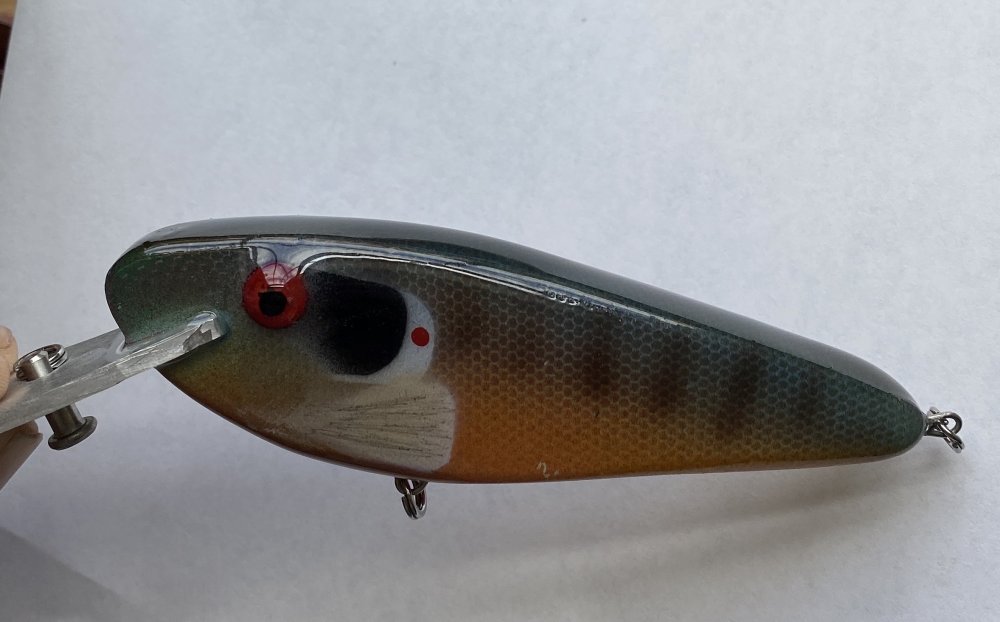
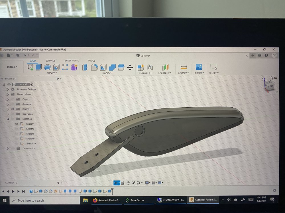
I am in the trial and error stages of digital crankbait making. This may be my first post on here, but your contributions to this site have provided answers to most of the questions I’ve had preventing the need to ask a bunch of questions. As far as I can tell, no one has documented the end to end process of building a lure with a CNC machine. I picked up a micro mill CNC off Craigslist last fall that was built in the late 90’s for very little cost. Using information from the internet, I have been able to get the machine, a cnc’d sherline mill operational on modern software. It’s stunningly precise in its movements for something like this I plan to make the attached crankbait on the attached CNC micro mill from the attached photo of the CAD design. I almost had the 1/8 inch thick aluminum lip cut last night but The depth of cut and feed rate was too aggressive and the bit started chattering and messed it up. The OP was running a very powerful, very rigid higher end CNC in my opinion. Probably a machine costing 10k+. if you’re truly interested, I’ll document the process and post on YouTube. This is going to be hard maple hollowed such that it floats with center of gravity in lower front third of the lure. The ‘software stack’ I have chosen is Fusion 360 for CAD, vCarve Desktop for 2d CAD/CAM and CAM of 3d profiles designed in Fusion 360 and Mach3 for machine control. I see the following benefits to building lures digitally: 1) Ability to control where the center of gravity is without trial and error. 2) Ability to make exact fit airbrush templates on 3d printer 3) Consistency. Once I have the basics down, I’ll be able to replicate the design and develop trolling depth charts for the lure (I’m a troller)